Simulation software is a powerful aid to new product development in industries as diverse as automotive, aerospace and medical devices. Finite Element Analysis (FEA) software, however, is both extremely expensive and complex to use, so those capabilities are not often available at the supplier level. And while OEMs may use simulations to test part design and function, metal stamping simulation software is used to determine whether the part will work as a metal stamping and how best to design and build the tool to produce it.
Metal stamping simulation software allows engineers to evaluate tool design options and simulate how the part will react with a variety of materials during metal stamping. By using simulation software, metal stamping engineers can help save their OEM clients money and time in the long run by designing the part for manufacturability. However, it takes considerable expertise to use FEA software effectively.
Simulating a range of materials at no additional charge
Metal stamping simulation software packages include a basic material library with specifications for standard materials used in metal stamping, such as stainless steel and aluminum. But with growing demand for new high-strength materials as well as rare and precious metals, the basic library of materials is not sufficient. For a metal stamping firm that produces both large parts and micro-assemblies, the material stock thickness may range from .0015 to .125 or more, while the width ranges from 1/4" up to nearly two feet.
Metal stamping firms that wish to go beyond the standard materials will pay for a lab to provide data on specific types of materials. Such lab reports may be required even for standard materials in order to cover the grades of materials and the hardness or temper of each.
The cost of simulation and material lab tests are generally not charged back to the customer, unless the OEM has requested specific simulations for its own use in new product design. Instead, the metal stamping firm will recover its costs by saving on tooling design and build expenses.
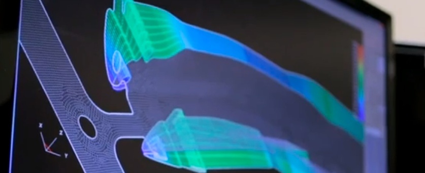
Running multiple iterations to evaluate performance and avoid problems
For a new part design that may test the limits of metal stamping, engineers may run anywhere from ten to 40 different iterations of a simulation, showing how a tool will form a part and whether the metal specified will work within those limits. Depending on the size of the simulation, the software may need to run for several hours or overnight.
Oftentimes, the simulation will reveal weak spots in the part design or indicate that the metal may crack or pull in production. Springback is a common problem with new high-strength, aluminum and magnesium, which must be addressed to avoid production programs.
Parts with simple specifications such as straight 90-degree angles, may not require simulation, while parts with complex geometries, such as linear bends and compound bends, do.
Simulation may also be used to evaluate existing tools that have exhibited borderline problems or experienced intermittent downtime, in order to identify how the tool can be fixed to improve production. Here, too, simulation software ultimately saves the OEM money by avoiding the expense and time delay involved in designing and building an entirely new tool.
Using virtual prototyping before actual prototyping to save money and time
Before metal stamping simulation software was available, the only choice for determining whether a part could be stamped efficiently was to develop a prototype of the tool design. The process of “soft tooling” involves making a low-cost tool, which can produce a small run of sample parts. Now, simulation software may serve as a virtual prototype. However, for a brand new product design, investing in both virtual and actual prototyping may be the best strategy to avoid potential quality problems down the road.
Tool design and build is the most critical step in metal stamping, as building the tool is a major investment of development time and money. By using simulation software in developing a tool, metal stamping engineers can spot problems before the tool is built and ensure that the tool will perform as required. The software can even offer unconventional tool designs, which may work better than more traditional approaches. As a result, the amount of tryout time can be reduced or eliminated.
Without simulation, a metal stamper would design the tool according to normal parameters, put it in the press, try it out in operation, and then make modifications as needed. Any changes to the tool, however, would likely be expensive and time-consuming.
The proper tool design also has a bearing on materials usage and waste, as well as the long-term durability of the tool itself, which are additional cost-saving factors. Cycle time is also affected if a tool fails to perform as needed.
Improving the part’s design with data to ensure manufacturability
Due to limited resources, many manufacturers will not go through the DFM process with every part of their new product, such as metal stampings. As a result, metal stamping engineers must evaluate the part’s design for manufacturability. If the DFM process indicates that a part needs to be redesigned, the OEM may resist, as the part’s configuration has an impact on the entire assembly.
Before metal stamping simulation software was available, manufacturers had to simply take the word of their metal stamping supplier who advised that the part design should be modified. Now, everyone can see the proof in the simulation. Metal stamping engineers can share simulation results to demonstrate how the part would or would not function during stamping. The simulation software also can suggest improvements to the part design, which can be reviewed and approved quickly and easily.